Badger Ordnance M5 Choate Tactical Stock Package Installation

Posted in DIY, Remington 700, Tactical Works Home on December 14th, 2010 by Team TW

WARNING


Warning!

Before starting work on any firearm be sure that the firearm is clear. Do not touch the trigger until the firearm has been cleared. Inspect the chamber to ensure that it is clear of ammunition and that there is no ammunition positioned to be chambered. Do not keep live ammunition near your workspace. Once you have checked the firearm, check it again!

Tactical Works, Inc. takes no responsibility for the accuracy and/or safety of this “how to”.  This post is simply for your reading enjoyment. Before shooting any firearm have it inspected by a qualified gun smith.

Installing the Badger Ordnance M5 Trigger Guard with the Choate Tactical Stock

Badger M5 Choate Installation

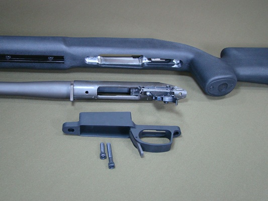
Until now installing a dropbox magazine on your Remington 700 ADL or BDL required sourcing all of the parts and then sending your stock off to a gunsmith to be inletted. This required paying to ship your stock, waiting, and then paying to have the stock sent back. Now you can order a complete solution that is bolt-on, out-of-the-box, and can be assembled in less than an hour without special tools.

Parts:

  • Choate Tactical Stock Inletted for the Badger Ordnance M5 Trigger Guard.
  • Badger Ordnance M5 Trigger Guard Kit. (kit includes trigger guard, 5-shot magazine, 2 #3o Torx screws, 2 aluminum pillars)

Badger M5 Choate Installation

Tools:

  • 5/32 Hex/Allan Key
  • #30-Torx Driver and/or Socket
  • Calibrated Torque Wrench

Time:

Less than one-hour.

Remove all optics and accessories that might get in the way or be damaged during installation. Our subject rifle is a Remington 700 PSS. The original floor plate has been replaced with a MagXtender however, installation is the same for rifles that  have the OEM floor plate.

Badger M5 Choate Installation

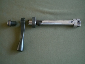
Remove the Bolt from the rifle. Press the Bolt Release button which is located in the top of the trigger guard in front of the trigger.

Badger M5 Choate Installation

While the Bolt Release button is depressed, slide the bolt all the way back until the bolt is free of the action. Set the bolt aside until ready to reassemble.
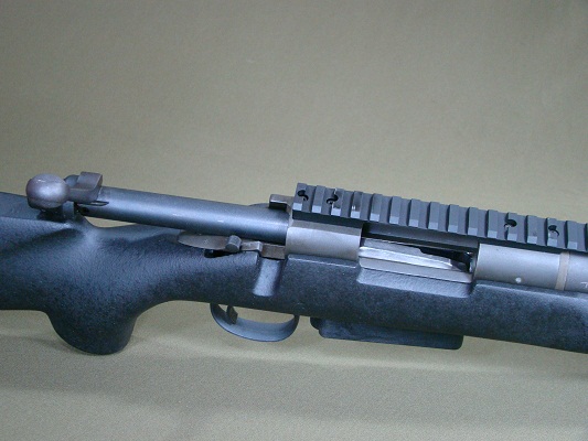
Badger M5 Choate Installation
Use a 5/32″ Hex key to remove the two trigger guard screws.
Badger M5 Choate Installation

Badger M5 Choate Installation

Once both action screws are removed, the trigger guard will be free from the original stock and barreled action. Gently pull the trigger guard from the stock while supporting the barreled action. Make sure the barreled action is supported or it will drop free from the stock and can be damaged.

Badger M5 Choate Installation

Remove the trigger guard and the internal magazine box from the stock. The entire trigger guard and internal magazine will not be reused. Remove parts from the workspace for the remainder of the installation. Remove the barreled action from the stock and place it out of the way as well. The stock will not be used again for this project.

Badger M5 Choate Installation

Gather the new Choate Tactical Stock, the Badger M5 Trigger Guard, and both of the supplied T-30 Action Screws and place them on your workspace. The supplied Badger Ordinance Pillars are not used for this application. This is due to the full length aluminum bedding block used in the Choate Tactical Stock.

Badger M5 Choate Installation

Place the barreled action into the Choate Tactical Stock. Supporting the barreled action, turn the rifle over and insert the Badger Ordnance M5 Trigger Guard into the inlet stock. Insert the longer of the two #30-Torx action screws into the rear of the trigger guard. The shorter of the two #30-Torx action screws installs in the front of the trigger guard.

Badger M5 Choate Installation

To get the action screws started, thread them by hand to avoid damaging the threads on the action screws and more importantly the action. Once the action screws are started, slowly and carefully tighten them equally taking time to make sure neither of the action screws are too long. If one or both of the action screws are too long you will need to either trim the supplied action screws or purchase new shorter screws. The action screws are a 7/28 thread that can be found at most chain hardware stores.

Badger M5 Choate Installation

When both action screws are snug and are the proper length to clear the bolt use a #30-Torx driver to torque them to 65 in-lbs. Caution! Failure to torque the action bolts with a calibrated Torx Driver may result in damage to the rifle! Per Badger, LocTite not needed.

Badger M5 Choate Installation

After installing the trigger guard double-check that the action screws will clear the bolt and install the bolt. Next insert the supplied Accuracy International 5-shot magazine into the Badger Trigger Guard. With the rifle unloaded cycle the bolt to make sure that the bolt cycles freely and does not hang up on the magazine.

Installation complete.


Tags: , , ,

Installation of the Magpul MOE Trigger Guard

Posted in AR15, DIY, Magpul, Tactical Works Home on April 25th, 2010 by Team TW
Magpul MOE Trigger Guard

Installing the Magpul MOE/Enhanced Trigger Guard

Flat hinged trigger guards  are standard equipment with most AR15s and AR Lower Parts Kits (LPK) and leave a little to be desired.   The annoying gap between the standard trigger guard and the grip can tend to get uncomfortable during long shooting sessions and needs to be “folded” open to accommodate larger cold weather gloves.

Read more »

Tags: ,

MAG-XTENDER Installation Remington 700

Posted in DIY, Remington MAG-XTENDER, Tactical Works Home on August 31st, 2009 by Team TW


Installed MAG-XTENDER

Installation of the MAG-XTENDER on a Remington 700

This page will help you understand how to install the MAG-Extender on a Remington 700. Our subject is a Remington 700 .308 PSS.

Read more »

Tags: , , , ,

Savage Tactical Bolt Handle Installation

Posted in DIY, Savage Tactical Bolt Handle on July 22nd, 2009 by Team TW
Savage Tactical Bolt Installed

Savage Tactical Bolt Handle

Tools:

1/4″ Allen Wrench

Time:
5-30 minutes

First and foremost, as always, Safety First!!!

Every time you handle a firearm make sure it is unloaded. Don’t take anyone’s word for it. Check it, and check it again!

Once you rifle is clear, the first step will be to remove the Bolt. To remove the Bolt press down on the Bolt Release Lever which is on the right of the action, while simultaneously pulling the Trigger.

Removing Bolt From Rifle

The Sear needs to clear the trigger. Once the Sear has passed the trigger you can release the Trigger and pull the Bolt free of the action.

With the Bolt out of the rifle use the 1/4″ Allen wrench to remove the Bolt Assembly Screw. Turn the Bolt Assembly Screw counter-clockwise until the Bolt Assembly Screw is free from the Bolt.

Removing the Bolt Assembly Screw

Take your new Tactical Bolt Handle and install it on the Bolt where the original Bolt Handle was. The new Tactical Bolt Handle will only go on two ways so this is pretty easy to figure out. If you do it wrong the first time spin the Bolt Handle 180 degrees and you should have it right. No need to mark it, just slide it over the Bolt and replace the Bolt Assembly Screw in the opposite direction used for removal (clockwise).

Installing the Tactical Bolt Handle on the Bolt

Once the Tactical Bolt Handle is on the Bolt, simple press pull the Trigger while pressing the Bolt Release Lever down. Once you feel the Sear clear the trigger you can release the trigger and slide the bolt into the action.

Sliding the new Tactical Bolt Handle into the Action

Sliding the new Tactical Bolt Handle into the Action

That’s it! Enjoy your new Tactical Bolt Handle!

**If the new bolt handles hangs up a little on the action, cycle the bolt a number of times and it should loosen up. Keep in mind you’re putting a brand new part on a used gun so it might take a little shooting to get new Tactical Handle to be as smooth as the stock bolt handle.

***Additional Note from Tony, a helpful customer.

 “When the bolt is removed the firing pin is in the cocked position and  the rear portion of the cocking piece sleeve protrudes into the bolt  assembly screw blocking the insertion of the 1/4″ Allen wrench.  To  continue disassembly  the firing pin must be released moving the  cocking  piece forward. This can be accomplished by using a 7/16” box wrench on  the cocking piece pin to move it over the cam portion of the bolt body,  releasing the firing pin.


 For reassembly, once the new bolt handle is installed and the bolt  assembly screw is tightened, the firing pin must be re-cocked in order  to insert the bolt into the receiver. Again, the 7/16″ wrench can  be used to move the cocking piece pin back over the cam in the bolt  body.


 While those with experience may know this already, it might be  advisable to add these steps in the online instructions for first time  installers.”

Tags: , , , , , ,

Just Added: Karsten Cheek Piece A-model installation Instructions

Posted in DIY, Karsten Adjustable Cheek Rest on January 26th, 2009 by Team TW

Link to Karsten A-Model installation page

Tools needed:

  • Handrill
  • 1/4 Drill Bit
  • Pencil

Karsten “A” Kit:

  • 1-Saddle
  • 2-1/4 bolts
  • 2-Lock wheels
  • 1-Rubber pad

Estimated Time:

  • Less than 1 hr.

The first step in the installation of the A-model is to decide where on the stock you want the rest to sit. On bolt action rifles make sure you can cycle and remove the bolt once the cheek rest is installed.

Checking placement and bolt clearance

The bolt is pulled all the way to the back of the action as if it is going to be removed for cleaning.

Check the placement and the bolt clearance a few times to make sure it fits and the bolt will clear the saddle.

Mark all 4 top hole locations (left and right side of the stock) with a pencil or other marking device that will be visible once the saddle is removed from the stock.

Holes marked for Karsten Cheek Piece Install
Holes marked for drilling

Once all 4 holes are clearly marked get our your hand drill. This is the tough part. You’re going to be drilling four, 1/4″ holes in your stock.  Don’t worry, if you’ve checked the bolt clearance and you like the position of the saddle on the stock, it will all come together.

The stock we’re adding the Karsten cheek piece to is the stock Savage “tupperware” model which, is hollow, foam filled plastic. The hollow plastic stock is very easy to drill through.

With your hand drill use a 1/4″ bit and place the bit in the center of your first mark and drill. Slower is better here. You may want to center punch the marks and drill a pilot hole if you’re a perfectionist. We didn’t and everything lined up nicely.

Drill all 4 holes (two holes on the left side of the stock and two on the right) until you are through the plastic and into the foam.

Drill each hole through the plastic into the foam.
Drill each hole through the stock into the foam.

After all four holes are drilled, slowly align the back two holes by passing the drill bit in one hole out the other. Repeat on front holes.

Clean out the holes by drilling through both holes

Once you’ve cleaned out the holes in the stock, wipe the debris off the stock and slide the saddle over the stock.  With the saddle on the stock simply insert the bolts through the holes, and thread the lock knobs on.

Optional:

Included in the kit is a sheet of 1/8th inch rubber that can be glued to the upper exterior surface for a better contact area with the cheek. If you are in hot conditions and/or wear face paint regularly  affixing the rubber sheet will give you a more consistent, no-slip, cheek weld.

Suggested glue is  3M 80 or Hi Strength 90 to glue rubber in place.

Finished Product
Finished Product
Tags: , , , , ,

Just added: Karsten Cheek Piece B-Model Installation Instructions

Posted in DIY, Karsten Adjustable Cheek Rest on January 26th, 2009 by Team TW

Link to Karsten B-Model Installation Instructions

Karsten Cheek Piece B-Model Kit

Tools needed:

  • Handrill
  • 1/4 Drill Bit
  • Pencil

Karsten “B” Kit:

  • 1-Saddle
  • 2-1/4 bolts
  • 2-Blind nuts
  • 1-Rubber pad

Estimated Time:

  • Less than 1 hr.

The first step in the installation of the B-model is to decide where on the stock you want the rest to sit. On bolt action rifles make sure you can cycle and remove the bolt once the cheek rest is installed.

Checking placement and bolt clearance

The bolt is pulled all the way to the back of the action as if it is going to be removed for cleaning.

Check the placement and the bolt clearance a few times to make sure it fits and the bolt will clear the saddle.

Mark all 4 top hole locations (left and right side of the stock) with a pencil or other marking device that will be visible once the saddle is removed from the stock.

Holes marked for Karsten Cheek Piece Install
Holes marked for drilling

Once all 4 holes are clearly marked get our your hand drill. This is the tough part. You’re going to be drilling four, 1/4″ holes in your stock. Don’t worry, if you’ve checked the bolt clearance and you like the position of the saddle on the stock, it will all come together.

The stock we’re adding the Karsten cheek piece to is the stock Savage “tupperware” model which, is hollow, foam filled plastic. The hollow plastic stock is very easy to drill through.

With your hand drill use a 1/4″ bit and place the bit in the center of your first mark and drill. Slower is better here. You may want to center punch the marks and drill a pilot hole if you’re a perfectionist. We didn’t and everything lined up nicely.

Drill all 4 holes (two holes on the left side of the stock and two on the right) until you are through the plastic and into the foam.

Drill each hole through the plastic into the foam.
Drill each hole through the stock into the foam.

After all four holes are drilled, slowly align the back two holes by passing the drill bit in one hole out the other. Repeat on front holes.

Clean out the holes by drilling through both holes

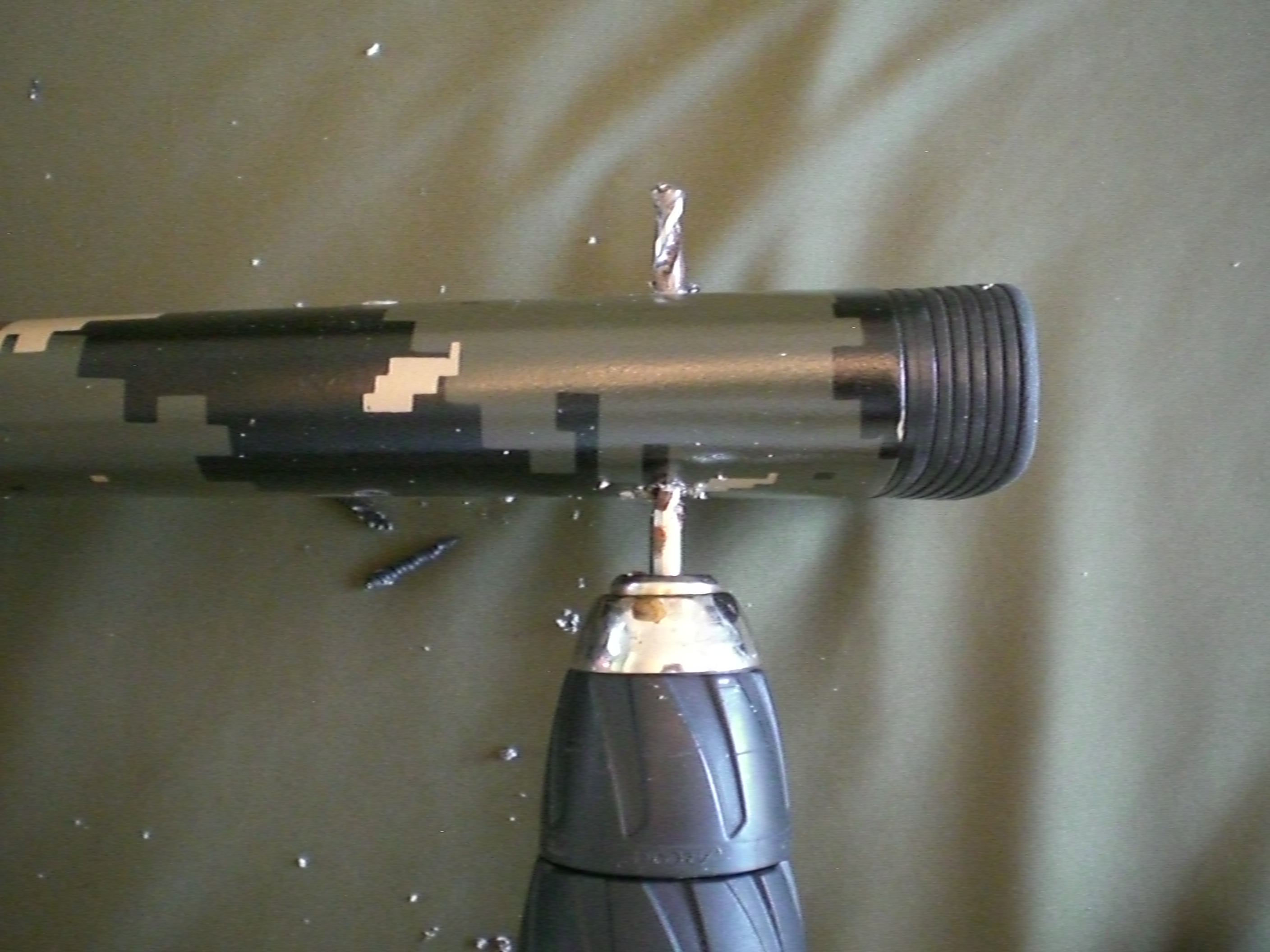
The B-Model is a little more work than the A-Model because of the blind nuts/inserts.  To accommodate for the width of the inserts it is necessary to expand the 1/4″ hole to a 3/8″ wide x 1/2″ deep in the left side (cheek side) of the stock.

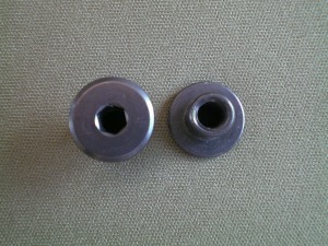
Allen insert 3/8" x 1/2"
Blind nut/insert 3/8″ x 1/2″

To do this use a 3/8″ drill bit and simply ream out the two existing holes on the left (cheek side) of the stock. Our example is again, the OEM Savage “tupperware” so we only needed to drill through the plastic which was pretty thin.

Drilling existing holes for the inserts.

Once your holes are done you’re ready to test fit the saddle and bolts. In many cases the bolts will need to be shortened to get the right fit. Our stock is pretty narrow so the bolts had to be shortened.

Bolts are sticking about 1/4 through the stock

To Shorten the bolts a hand grinder was used to trim off about 1/4″ of the bolts.

Mark the threads where they need to be cut down. We needed to trim about 5 threads off each bolt. We cut the bolts flush with the stock.

The bolts were marked by threading on a nut to where the cuts need to be. The nuts were then taped into place with painters tape. The cuts were made with the bolts out of the stock. After the cuts, the tape was removed and the bolt was backed off to clean up the threads. CAUTION! The bolts do get hot. Wear gloves or let the bolts cool before handling.

Slide the saddle back on the stock, run the bolts through the saddle and stock then thread on the blind nuts/inserts.  If the bolts are still to long do a little more trimming and repeat until you achieve a good fit.  If the bolts can be tightened enough to secure and hold the cheek piece in position you’re done. Adjust the saddle to your liking, tighten the inserts with a 3/16″ allan/hex key and go shooting!

Optional:

Included in the kit is a sheet of 1/8th inch rubber that can be glued to the upper exterior surface for a better contact area with the cheek. If you are in hot conditions and/or wear face paint regularly affixing the rubber sheet will give you a more consistent, no-slip, cheek weld.

Suggested glue is 3M 80 or Hi Strength 90 to glue rubber in place.

Karsten Cheek Rest B-Model Finished
Tags: , , , , ,

Karsten’s Tips and Tricks

Posted in DIY, Karsten Adjustable Cheek Rest on January 22nd, 2009 by Team TW
Karsten Cheek Piece Tips and Tricks

Karsten Cheek Piece Tips and Tricks

Link to Karsten’s Tips and Tricks
I use a drill press as it makes it a lot easier keeping everything plumb. I also use a small torpedo level (6 inch plastic available at Home Depot if you don’t have one for about $4.00, good ones run about $12.00)

I loop a rubber band over one end of the level, place the level on the stock and loop the rubber band under the stock and the other end of the level.

Place the level on the flat portion of the stock just forward of the wrist.

Drill 1/4 inch hole straight through keeping the stock as level as possible while drilling.

SIMPLE Method for use with hand drills.

Position cheek piece and mark for holes on each side. Drill one side half way through

The stock, turn over and drill the other side the rest of the way though.

Elongate one hole should you be off a little after drilling for easier installation.

Note, if you mess up and get a little off on one or both holes just elongate one of the holes horizontally. This will give you some play front to back but still remain secure as the one hole is 1/4 inch.

You will need to counter sink up side of the stock to open the hole up to 3/8 inch but only to a depth of and 3/8’s of an inch. (Only applies to Flush Insert style)

With Insert style adjusters it may/will be necessary to shorten bolt due to varying width, placement or style stock.

Included you will also find 1 piece of 1/8th inch rubber that can be glued to the upper exterior surface for a better contact area with the cheek.

I use 3M 80 or Hi Strength 90 to glue rubber in place.

*If you find the cheek pieces tight on your stock, boil some water and heat the upper surface up and open up gently to fit.

** IMPORTANT, For Bolt Action stocks check the desired position while cycling the bolt at varied heights. Also check to see if you can remove the bolt without lowering or removing the cheek rest if that is important to you.

On AR15 type rifles be sure to drill the through holes lower than the buffer tube and check that the charging handle operates correctly and not blocked by the cheek rest.

Most claim it take 5 to 10 minutes.

Tags: , , , , ,